Selfmade stackmat display

  • Thread starter Thread starter fw
  • Start date Start date
any news? if you tell us which capacitors and resistors to use, it would be good :)
No, no news so far, sorry. I will do my best if I have some free time soon. You will need five 7 segment LED displays with (important) common cathode, NOT common anode. Then you will need some (at least 5, but order some more, they are cheap) 1µF electrolytic capacitors, a socket for the stackmat cable (I think its 2.5 or 3.5mm), an Atmel Atmega 88 Microcontroller, an Maxim MAX232 Level shifter, a Maxim MAX7219 Display Driver (which is not really necessary, you could multiplex the displays yourself, but that requires some software modifications), some 10K resistors (at least two I think), some 100 nF ceramic capacitors (at least 5 I think), some LEDs (pretty much doesnt matter what color or what type, just get the appropriate resistors for them (datasheet!)), some buttons (for stuff like "delete time", "save time", etc.), some switches (power switch, I like toggle switches), some diodes (4004 for example), an 7805 voltage stabilizer (looks like this, get the left one))...

Well, I did not make a schematic yet and I am sure there is something missing... I recommend if you cant wait, order the 7 segment LED displays and wait for my tutorial before you order the other stuff... The 7 segment dispalys need some searching.. Some stores are quite expensive.. Some are quite cheap.. Usually, the red ones are the cheapest.. I found some nice black ones with red LEDs, about 4cm height, for less than a dollar... Thats a good price :-)
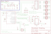
 
I took some time to draw a schematic today (file is attached).

This is just a first version! I am sure there are some mistakes that I will correct later when I notice them. The ISP socket is only necessary if you intend to program the microcontroller yourself (and of course, this circuit wont do anything without a software on the controller, which I will publish later).
 

Attachments

  • stackmat.png
    stackmat.png
    55.7 KB · Views: 91
thanks :)

I thought it would be simpler...:D

but looks like you have a lot of "extra stuff", like buttons and status leds, average calculations and so...

I wanted to do just a display, only to show the time, like the original one...
would be much easier, right?
 
well, you dont need the ISP socket and you dont need the LEDs and buttons. If you have a power supply, which gives you exactly 5 volts, you dont need the power supply circuit either.

I know, it looks a bit complicated, but trust me, it is not that hard. The Power supply circuit is very useful. You plug anything which gives you about 9V or higher (a battery, some old mobile power adapter, anything you like, doesnt matter) and you get exactly 5V output (which is the needed voltage for the microcontroller). The MAX232 adapter is the "heart" of this thing, it regulates the voltage the stackmat gives you (a "RS232" signal, the same every serial line a computer uses) and converts it down to 0V/5V, which the microcontroller can understand.

Dont be scared. I will create a display and make some pictures, you will see, its not that much hardware. Dont worry about the costs either.. All together, this circuit costs about 15 to 20 dollars, depending on the price of the LED displays..

And yes, the CAD software is Eagle.
 
well most of us don't even know what those things are, can you make a list of what we will buy, and a video tutorial maybe?
 
well, I am not going to tell you, that you can rebuild this thing without any knowledge in electrical engineering, but I promise you, that its not as hard as it looks.. I will see what I can do :-)
 
can you make this a stand alone timer? that is, you do not need stackmat for it to display your times...
 
I have seen the schematics, looks professional. Are you a practising engineer?

I have some queries, can we use say 4 x AA batteries making 6 volts, instead of the 5 volts indicated, How long would battery like this last?

Second query, using ISP socket how do you download the file into the microcontroller.

Can you post a Bill of Materials? What do you use for the prototype PCB?

Thanks in Advance
 
i think he used pcb 401 for his prototype, but of course you can make your own pcb layout, and fabricate your own pcb
 
Thanks, but no, I am not a professional.. I study computer science, but actually, I just started 2 or 3 months ago with microcontrollers (that should be an indicator to you, that it does not need years of experience to build (or rebuild) such stuff).

I am not planning to build a stand alone timer, sorry.. Not yet.. BUT, hm, nice idea.. Since I already know the stackmat protocol (the way the stackmat communicates with the stackmat display), that would be a nice idea for a next project.. I could build a stand alone timer, which can communicate with my selfmade display AND with the original display (since they "speak the same language") :-) But first I want to finish this thing, and this is "display only (with some goodies)" :-)

The prototype board you can see in the video is in german called "lochraster", its a special type of board with holse in a grid and contacts on the back, especially for "rapid prototyping", its not etched or something like a real pcb layout.. Here is a bigger bicture..

I dont know how long battery will last.. I will try this when its done.. I hope its long enough.. The microcontroller itself needs exactly 5V or a power regulater which creates 5V from anything higher than about 7.. You could use something like this I suppose.. But I am not 100% sure..
 
Last edited:
i think it is better to use the max232 voltage regulator, it is more reliable, it is used for stability of the circuit especially if you are using microcontrollers.
 
Back
Top