
Hi, i saw a mod video about an already backlit cube where the guy hacked it to make it on with a switch.... I wanted to try this mod on a good speed cube: like this one maybe. using micro LEDs and tiny watch batteries and wrap them around the core. and integrate a micro switch as well in there to turn it on. Can it be done? micro leds light up pretty bright with 2,3 small watch batteries.... and if the cube has got a decent amount of space in the core i think it could work. Let me know what you think. These cubes are expensive (atleast for me...i play with a $3.89 cube, which is cyclone boys) . i could buy one if i'm 100% sure this mod would work out.

Navigation
Install the app
How to install the app on iOS
Follow along with the video below to see how to install our site as a web app on your home screen.
Note: This feature may not be available in some browsers.
More options
Style variation
You are using an out of date browser. It may not display this or other websites correctly.
You should upgrade or use an alternative browser.
You should upgrade or use an alternative browser.
Led backlit speedcube
- Thread starter martin68
- Start date

newtonbase
Premium Member
This one is cheaper and is decent.
http://www.championscubestore.com/index.php?main_page=product_info&cPath=235&products_id=2253
http://www.championscubestore.com/index.php?main_page=product_info&cPath=235&products_id=2253

Electronics is my field, I say its achievable, but tricky.
There's not any real space in a modern cube's core region, you'd have more luck with older Rubiks-like ones.
However there is space inside the cubies, specifically the centre-pieces, which could contain your button cell(s). I've just had a quick peek in my Zhanchi, there's room in there. And an on/off switch could be fitted under the cap of the centre-piece. Obvious solutions include using a slide-switch, remove the cap to turn it on/off. Or use a micro-switch that's activated by the cap, so when the cap is on, the switch is closed, and the lights are on. You can get tiny switches like this from old PC CD-ROM drives and floppy disk drives. You could even homebrew a switch. Other possibilities include using a removeable jumper link, like the 2mm pitch types used in PC's for configuring stuff like hard disk master/slave select etc.
White LED's need about 3.0 Volts to drive them, so three common alkaline/silver-oxide/zinc-air type cells in series (total about 4 V ), with a suitable dropper resistor will work OK. Or a single Lithium cell typically 3.6 V, plus resistor would also work, there are small diameter Li cells, they're not common, CR1025 size may be suitable.
Fitting all that gear inside every centre-piece isn't realistic, but two opposite centres may work OK.
Small white LED's can be salvaged from old cellphones, used to backlight the screen and keyboard.
See how you get on, keep us updated.
There's not any real space in a modern cube's core region, you'd have more luck with older Rubiks-like ones.
However there is space inside the cubies, specifically the centre-pieces, which could contain your button cell(s). I've just had a quick peek in my Zhanchi, there's room in there. And an on/off switch could be fitted under the cap of the centre-piece. Obvious solutions include using a slide-switch, remove the cap to turn it on/off. Or use a micro-switch that's activated by the cap, so when the cap is on, the switch is closed, and the lights are on. You can get tiny switches like this from old PC CD-ROM drives and floppy disk drives. You could even homebrew a switch. Other possibilities include using a removeable jumper link, like the 2mm pitch types used in PC's for configuring stuff like hard disk master/slave select etc.
White LED's need about 3.0 Volts to drive them, so three common alkaline/silver-oxide/zinc-air type cells in series (total about 4 V ), with a suitable dropper resistor will work OK. Or a single Lithium cell typically 3.6 V, plus resistor would also work, there are small diameter Li cells, they're not common, CR1025 size may be suitable.
Fitting all that gear inside every centre-piece isn't realistic, but two opposite centres may work OK.
Small white LED's can be salvaged from old cellphones, used to backlight the screen and keyboard.
See how you get on, keep us updated.
...
Small white LED's can be salvaged from old cellphones, used to backlight the screen and keyboard.
See how you get on, keep us updated.
Where do you think i got the leds?
 salvaged 2 from old cellphone keypad ..that was when i got the idea...will start the project once i get a cube with decent interior space...for switch i may use this one . would be fine right? Led's if i would need more i could use these. also what resistors do you recommend? i would prefer micro ones... im not electronic guy...but i have some soldering skills and can always learn.
i found 2 transparent cheap cube with decent interior space. yj sulong and yj guanlong. which one do i go with?
That switch looks promising, another one that's commonly seen listed on eBay is this SMD one:
http://www.ebay.com/itm/10pcs-MSK-1...781334?hash=item2c7fafb016:g:uywAAOSwq7JT4jcF
Resistors...hmmm. That depends on how bright you want it. If you've wanting to cube in low light, running the LEDs at 3 mA is probably OK, and the battery will last a reasonable time. For daylight use, the current would need increasing to 10 mA maybe more, which is not good for little button cells.
Resistor value is calculated like this:
R = ( battery voltage - 3 ) / current
So for example 4 V from 3 button cells, and 2.5 mA LED current would work out as 400 Ohms. So you would choose 390 Ohms, but 330, 360, 430, 470 would all do the job.
You can get small leaded resistors, about 5mm long, usually referred to a 1/8th watt types. If you're going to use SMD ones, use larger ones, like 1206 or 0805 size, they are easier to work with and slightly more robust.
If you're not familiar with resistor marking codes (look online for detailed guides) the 390 Ohm part would be labelled as '391', meaning "3,9, one additional zero". Hence '101' = 100 Ohms, '471' = 470 Ohms, '102' = 1000 Ohms...etc.
To join up all your parts, I recommend thin wire, it stresses the components less. 0.2mm diameter is OK, it's a common size, used in wires like 7 / 0.2 = 7 strands of 0.2mm tinned copper wire, PVC insulated. You may have U.S spec wires, AWG, so just use what seems best.
http://www.ebay.com/itm/10pcs-MSK-1...781334?hash=item2c7fafb016:g:uywAAOSwq7JT4jcF
Resistors...hmmm. That depends on how bright you want it. If you've wanting to cube in low light, running the LEDs at 3 mA is probably OK, and the battery will last a reasonable time. For daylight use, the current would need increasing to 10 mA maybe more, which is not good for little button cells.
Resistor value is calculated like this:
R = ( battery voltage - 3 ) / current
So for example 4 V from 3 button cells, and 2.5 mA LED current would work out as 400 Ohms. So you would choose 390 Ohms, but 330, 360, 430, 470 would all do the job.
You can get small leaded resistors, about 5mm long, usually referred to a 1/8th watt types. If you're going to use SMD ones, use larger ones, like 1206 or 0805 size, they are easier to work with and slightly more robust.
If you're not familiar with resistor marking codes (look online for detailed guides) the 390 Ohm part would be labelled as '391', meaning "3,9, one additional zero". Hence '101' = 100 Ohms, '471' = 470 Ohms, '102' = 1000 Ohms...etc.
To join up all your parts, I recommend thin wire, it stresses the components less. 0.2mm diameter is OK, it's a common size, used in wires like 7 / 0.2 = 7 strands of 0.2mm tinned copper wire, PVC insulated. You may have U.S spec wires, AWG, so just use what seems best.
Last edited:
@SenorJuan lets say i want to add 2 Leds... i would wire them in series so they get same voltage. right? i plan to add these components: 2 micro leds, 3 button cell(gonna try to find the smallest possible one) , 1 micro switch, and a resistor. link me to the resistor i would need. assume i would be using the LEDs from the ebay link i posted above. they come with pretty long thin wires...i could use that itself.
i already have a sulong that once i got for free from lightake...i had forgotten its name....maybe i could try the mod on that itself before going to buy the transparent version....i found 2 transparent cheap cube with decent interior space. yj sulong and yj guanlong. which one do i go with?
If you're wanting to use two LED's in the same circuit, you're going to have to wire them in parallel, that is anode to anode, cathode to cathode, then choose your resistor for double the current, eg. 2 x 2.5 mA = 5 mA.
Try and use the largest button cells you can, they will have the greatest capacity (energy storage), will last the longest, and will be more economic.
Resistors, try salvaging them from junk computer etc boards. Or buy a 'development kit' of assorted values, a search for 'SMD resistor kit' produces such listings as:
http://www.ebay.com/sch/i.html?_odk...r+kit.TRS0&_nkw=smd+resistor+kit&_sacat=92074
http://www.ebay.com/itm/400Pcs-0805...216632?hash=item54191765b8:g:F4cAAOSwq7JUG-XM
Try and use the largest button cells you can, they will have the greatest capacity (energy storage), will last the longest, and will be more economic.
Resistors, try salvaging them from junk computer etc boards. Or buy a 'development kit' of assorted values, a search for 'SMD resistor kit' produces such listings as:
http://www.ebay.com/sch/i.html?_odk...r+kit.TRS0&_nkw=smd+resistor+kit&_sacat=92074
http://www.ebay.com/itm/400Pcs-0805...216632?hash=item54191765b8:g:F4cAAOSwq7JUG-XM
Last edited:
i just tried several cell button sizes from different watches. SR521SW is the biggest i could fit on one axis without affecting cube movement...and its pretty small....it dosnt matter...i wont be playing with it all the time....i would be lucky if it could last even 1 week.Try and use the largest button cells you can, they will have the greatest capacity (energy storage), will last the longest, and will be more economic.
there will be 3 of them...would that increase the capacity.... to about 9-12 hours...lets say....20 minutes on per day.... lets not worry about battery life atm521's are 5.8mm diameter x 2.2mm thick, pretty small. And capacity is about 15 mAh, meaning it will provide 3 mA for 5 hours (more like 3 or 4 hrs in reality).
whats the danger if i dont use resistor? and now that that i check the led on ebay....these are the specs: Brightness: 720-900 MCD
Color Temperature: 3000K
Current: 20MA
Voltage: 3.0-3.2 (V)
they use way more current than you said. 3 ma but they use 20 here...also the voltage required is lower
I see I'm taking you beyond your skill level here..
Having 3 cells in series (nose-to-tail) means the voltage goes up three-fold, but the capacity remains unchanged. So the run-time is still a few hours.
The resistor is vital, to control the current. Without it, you'll get a very bright LED, a warm battery and a flat battery in no time at all. And maybe a duff LED.
Now LED specs, it's way more complimacated than you would think, there's: total output, brightness, perceived brightness depending on the colour; manufacturers specify these characteristics at different currents blahblah.
The 900 mCd figure is what is produced when you pass 20 mA through it. How much current is used is entirely up to you, and your series resistor choice. If you use less current, the brightness drops in proportion, eg. at 2 mA, expect 90 mCd.
900mCd is pretty bright, they may be similar to the ex-phone ones you have, at the same 20 mA current.
They look suitable for this project, anyway.
Also, zinc-air types have greater capacity, eg. the equiv of the silver cell you mentioned is 40 mAh:
http://www.smallbattery.company.org.uk/sbc_za5.htm
Here's a summary of common Ag button cells. See if you think larger cells might fit, eg.376,361,396, these would last longer, and cope with the high current draw better. They're designed for watches, mainly, ie 1 year drain-time, not 5 hours.
http://www.renata.com/industrial-products/silver-oxide-coin-cells/
Having 3 cells in series (nose-to-tail) means the voltage goes up three-fold, but the capacity remains unchanged. So the run-time is still a few hours.
The resistor is vital, to control the current. Without it, you'll get a very bright LED, a warm battery and a flat battery in no time at all. And maybe a duff LED.
Now LED specs, it's way more complimacated than you would think, there's: total output, brightness, perceived brightness depending on the colour; manufacturers specify these characteristics at different currents blahblah.
The 900 mCd figure is what is produced when you pass 20 mA through it. How much current is used is entirely up to you, and your series resistor choice. If you use less current, the brightness drops in proportion, eg. at 2 mA, expect 90 mCd.
900mCd is pretty bright, they may be similar to the ex-phone ones you have, at the same 20 mA current.
They look suitable for this project, anyway.
Also, zinc-air types have greater capacity, eg. the equiv of the silver cell you mentioned is 40 mAh:
http://www.smallbattery.company.org.uk/sbc_za5.htm
Here's a summary of common Ag button cells. See if you think larger cells might fit, eg.376,361,396, these would last longer, and cope with the high current draw better. They're designed for watches, mainly, ie 1 year drain-time, not 5 hours.
http://www.renata.com/industrial-products/silver-oxide-coin-cells/
Last edited:
i was able to fit 3 LR41 in between the axis's. and yes my level in electronics is that of a baby LR 41 has a capacity of about 25-32mah(google told me). this should be fine. right? now i need a resistor of 390ohm u say....gonna go find some old electronics laying around to find it. batteries would be lined up in series...leds in parallel. wouldnt i need 2 resistors then? for each led. again correct me if im wrong...thx for taking time helping me
LR 41 has a capacity of about 25-32mah(google told me). this should be fine. right? now i need a resistor of 390ohm u say....gonna go find some old electronics laying around to find it. batteries would be lined up in series...leds in parallel. wouldnt i need 2 resistors then? for each led. again correct me if im wrong...thx for taking time helping meAttachments
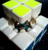
Oooh, interesting pic, I wasn't expecting that, I thought you were putting then in a centre-piece, oh well.
Lucky there's no torpedoes to get in the way with that cube.
So some new thoughts - there's technically 6 'slots' for cells, maybe if you're only filling 3, space the cells about evenly. You could fit 3 LEDS in parallel in the other 3 'slots'. Don't be afraid to slighly cut into the core (file, Dremel tool etc) if it helps seat the button cells in better/deeper.
Ideally, it is best to use a seperate resistor for each LED. Parallelling them up is a component-saving cheat, if the LEDs are identical, then it works OK.
As you're just testing a concept, don't be too critical about resistor choice, something in the 200 Ohm to 680 Ohm range will get you started, then tinker from there. There's always the possibility of using resistors in series or parallel to get different values. Eg. you may find some circuit board with loads of '101' = 100 Ohm R's on it, two or three of them in series might serve you well.
This article may be illuminating hoho.
https://learn.sparkfun.com/tutorials/light-emitting-diodes-leds
Lucky there's no torpedoes to get in the way with that cube.
So some new thoughts - there's technically 6 'slots' for cells, maybe if you're only filling 3, space the cells about evenly. You could fit 3 LEDS in parallel in the other 3 'slots'. Don't be afraid to slighly cut into the core (file, Dremel tool etc) if it helps seat the button cells in better/deeper.
Ideally, it is best to use a seperate resistor for each LED. Parallelling them up is a component-saving cheat, if the LEDs are identical, then it works OK.
As you're just testing a concept, don't be too critical about resistor choice, something in the 200 Ohm to 680 Ohm range will get you started, then tinker from there. There's always the possibility of using resistors in series or parallel to get different values. Eg. you may find some circuit board with loads of '101' = 100 Ohm R's on it, two or three of them in series might serve you well.
This article may be illuminating hoho.
https://learn.sparkfun.com/tutorials/light-emitting-diodes-leds
Last edited:
Similar threads

- Replies
- 24
- Views
- 3,684


- Replies
- 10
- Views
- 1,822


