V-cube misallignment problem - solved

attachment.php

I shall try to explain using these diagrams. Honestly, I got it the second time looking through the diagrams on the first page.

Okay, first, this works exactly with the same principle as the pin mod, making the center piece catch on an attachment on the rivet/screw, causing the center to turn along with the center piece its caught on to.

In the first picture, it shows a rivet/screw with the attachment. From what I think it is from very brief reading, its a metal piece that is soldered or whatever onto the rivet/screw. The next picture(to its right) shows how a center piece sits on the rivet/screw with the attachment.

Notice how the pin mod creates a sort of track under the center piece? This is the same, except you just cut of a chunk right away.

The next picture(to its right) shows which 1/4 of the rivets/screws this attachment is put on.

The picture below it, shows how it works. When turning a layer, one center piece will catch on to the attachment. This will cause the center piece to stick to that center piece, much like how the pin mod works. The other center pieces are then free to move around.

The 2 pictures on the right most show what happens when the layer that sits on the rivet/screw is turned. Remember that chunk that was cut off? That will allow the attachment to simply slide under the centers when turned.

I hope this helps explain the mod. I can definitely see the ease of mass production with this way compared to mass producing with pin mods.
 
Hi,

I missed this thread. I have thought at a similar solution a long time ago. However, we have a major problem here : we have to loose the « elasticity » of the cube, sollowed by spring.

This also make a cube that you cannont adjust.

However, we can do the trick from the center with major structural change. I think it's better to do the trick on inner wings than center, but it require much more modifications.

The big speher in the center formed by edges and corners have to be reduced. Like in a rubik 4x4x4. Then the internal sphere can be attached to the structure and railroad graved on it.
 

I shall try to explain using these diagrams. Honestly, I got it the second time looking through the diagrams on the first page.

Okay, first, this works exactly with the same principle as the pin mod, making the center piece catch on an attachment on the rivet/screw, causing the center to turn along with the center piece its caught on to.

In the first picture, it shows a rivet/screw with the attachment. From what I think it is from very brief reading, its a metal piece that is soldered or whatever onto the rivet/screw. The next picture(to its right) shows how a center piece sits on the rivet/screw with the attachment.

Notice how the pin mod creates a sort of track under the center piece? This is the same, except you just cut of a chunk right away.

The next picture(to its right) shows which 1/4 of the rivets/screws this attachment is put on.

The picture below it, shows how it works. When turning a layer, one center piece will catch on to the attachment. This will cause the center piece to stick to that center piece, much like how the pin mod works. The other center pieces are then free to move around.

The 2 pictures on the right most show what happens when the layer that sits on the rivet/screw is turned. Remember that chunk that was cut off? That will allow the attachment to simply slide under the centers when turned.

I hope this helps explain the mod. I can definitely see the ease of mass production with this way compared to mass producing with pin mods.

thank you very much for explaining this for me, i have had a very hard time trying to explain in my poor english with revalent sentences.

just one more thing to add, this mod should work smoother that the pin mod because in the pin mod the pin "catches" on the center, so if you turn the face it might also turn the rivets. this mod simply holds onto the pieces so it could glide smoother than the pin mod when turning the face.
 
However, we have a major problem here : we have to loose the « elasticity » of the cube, sollowed by spring.

false

This also make a cube that you cannont adjust.

True, but you neither are the pin-modded cubes. And the V-cubes are not adjustable anyway.
If you really want an adjustable cube, we could always come up with some extensions that allows the notch to stay fixed while adjusting the cube.

However, we can do the trick from the center with major structural change. I think it's better to do the trick on inner wings than center, but it require much more modifications.

you mean the inner center edge?

The big speher in the center formed by edges and corners have to be reduced. Like in a rubik 4x4x4. Then the internal sphere can be attached to the structure and railroad graved on it.

i seems to have failed to understand what you mean. care to explain it in simpler English?


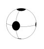
another type of screw-spring 4x4 i have thought of is replacing the ball core of a Rubik's 4x4 with a spherical 2x2. A picture is worth a thousand words:

attachment.php
 

Attachments

  • Ballz.JPG
    Ballz.JPG
    8 KB · Views: 103
However, we have a major problem here : we have to loose the « elasticity » of the cube, sollowed by spring.

false

No ! Think about it. The extention on the spring is very centered. So if the center can move a little from the centered position, you can end with an horrible situation with a misaligned structure that remain locked because of the additions on the spring.

I nevers thought about the 2x2x2 structure. This is very smart :D I like the idea. Does anyone already has realized something like this ?
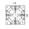
Ok, let's explain my idea I little bit more. The idea isn't that simple to explain.

On a V-cube like strcture, the edges (so inner edge, otherwize I'll call them wing instead of edges) and corner pieces are making a sphere around the core.

The idea is to remove this sphere and just keep the surface of it to disallow edges and corners to pop. Then replace this sphere by another one, and put railroad in it.

I have joined some images becuse it's quite hard to explain. So in black, the new inner shpere, in red, the outer sphere with asymetric railroad in it (to keep structure aligned) and in green, the symetric railroad (to allow face turn).

You'll see that the center piece is modified also :
attachment.php

attachment.php


The image I start from is taken from V-cubes patent - european version.

However, this idea doesn't scale very well. I have another version for nxnxn even cube, but I'm too lazy to make picture of it. I really suck at this !
 

Attachments

  • vcube struct.png
    vcube struct.png
    4.4 KB · Views: 84
  • vcube mod.png
    vcube mod.png
    6.3 KB · Views: 84
Last edited:
However, we have a major problem here : we have to loose the « elasticity » of the cube, sollowed by spring.

false

No ! Think about it. The extention on the spring is very centered. So if the center can move a little from the centered position, you can end with an horrible situation with a misaligned structure that remain locked because of the additions on the spring.

No! Think about it. Would doing the pin mod turn a V-Cube into an Eastsheen??

EDIT: i guess you meant that if the cube is loose the center piece could "lift" slightly and the inner slice still misalligns.
You are right, but the pin mod also have this kind of problem in your condition. However, there is no need to worry because if the cube is loose enough to make that happen, it would be a cube that pops every single turn you make. Big cubes does not need a wide adjustment range, so you don't really need to worry about the misalligning problem.

I nevers thought about the 2x2x2 structure. This is very smart :D I like the idea. Does anyone already has realized something like this ?
actually, i think this is a very obvious idea. im sure that a lot of people would have already thought about it.

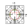
Ok, let's explain my idea I little bit more. The idea isn't that simple to explain.

On a V-cube like strcture, the edges (so inner edge, otherwize I'll call them wing instead of edges) and corner pieces are making a sphere around the core.

The idea is to remove this sphere and just keep the surface of it to disallow edges and corners to pop. Then replace this sphere by another one, and put railroad in it.

I have joined some images becuse it's quite hard to explain. So in black, the new inner shpere, in red, the outer sphere with asymetric railroad in it (to keep structure aligned) and in green, the symetric railroad (to allow face turn).

You'll see that the center piece is modified also :
attachment.php

attachment.php

Neat idea!! So this is basically a ball core mech, but with the center pieces supporting the structure instead of corner centers locking into the groove. The spring could still function this way, and have the middle slices locked dead. I'm very sure this would be much more practical for mass producing than my screw/rivet mod.

HOWEVER! We runs into another problem is that the inner layer will have zero tolerance. So this is still like the ball core 4x4s: Awesome tolerance on the outer layer, and no cutting ability on the innner layer.


PS: just to let you know, there really isn't a "ball" in the V-Cube; i believe you meant "removing a ball-shaped chunk".
 
Last edited:
If you want to remove the click mechanism, can't you just do the pi mod gluing the small internals that ride the core and just do four of these on the screws that you would normally glue pins into?
no, think about it. when the center with glued pieces turns 90 degrees the cube will get stuck.

[OFF-TOPIC] Also, would soldering my pins be a good idea? I'm scared of cutting them too short like last time I glued them in...

You could always remove the solder with your fingernails..
 
EDIT: i guess you meant that if the cube is loose the center piece could "lift" slightly and the inner slice still misalligns.
You are right, but the pin mod also have this kind of problem in your condition. However, there is no need to worry because if the cube is loose enough to make that happen, it would be a cube that pops every single turn you make. Big cubes does not need a wide adjustment range, so you don't really need to worry about the misalligning problem.

That's exactly what I meant :D

I think this is more misalign prone than Pi mod. It depend how you glue the pin, but it is possible to have a better configuration here.

However, If a misalignement occurs, We are in deep trouble with this kind of structure I guess.

I nevers thought about the 2x2x2 structure. This is very smart :D I like the idea. Does anyone already has realized something like this ?

actually, i think this is a very obvious idea. im sure that a lot of people would have already thought about it.

Neat idea!! So this is basically a ball core mech, but with the center pieces supporting the structure instead of corner centers locking into the groove. The spring could still function this way, and have the middle slices locked dead. I'm very sure this would be much more practical for mass producing than my screw/rivet mod.

HOWEVER! We runs into another problem is that the inner layer will have zero tolerance. So this is still like the ball core 4x4s: Awesome tolerance on the outer layer, and no cutting ability on the innner layer.


PS: just to let you know, there really isn't a "ball" in the V-Cube; i believe you meant "removing a ball-shaped chunk".

Thank you for liking it :D

I have made the drawing quite fast but things can be better than it seems for inner slices. First of all, the red rail can be larger than the center piece. Just 1 piece on 4 have to be locked properly.

Have a look at the picture. Only the green part have to be tight, the others rail can be larger than the center piece to keep cube tolerance.

attachment.php


This trick can also be done on edges instead centerpiece. It require twice as many tracks on the core ball. This would also allow much more tolerance, but I'm too lazy to draw it. This is very similar anyway and i'm pretty sure you can decuce it from the center pattern.
 

Attachments

  • railroad.png
    railroad.png
    2.8 KB · Views: 97
EDIT: i guess you meant that if the cube is loose the center piece could "lift" slightly and the inner slice still misalligns.
You are right, but the pin mod also have this kind of problem in your condition. However, there is no need to worry because if the cube is loose enough to make that happen, it would be a cube that pops every single turn you make. Big cubes does not need a wide adjustment range, so you don't really need to worry about the misalligning problem.

That's exactly what I meant :D

I think this is more misalign prone than Pi mod. It depend how you glue the pin, but it is possible to have a better configuration here.

However, If a misalignement occurs, We are in deep trouble with this kind of structure I guess.

I nevers thought about the 2x2x2 structure. This is very smart :D I like the idea. Does anyone already has realized something like this ?

actually, i think this is a very obvious idea. im sure that a lot of people would have already thought about it.

Neat idea!! So this is basically a ball core mech, but with the center pieces supporting the structure instead of corner centers locking into the groove. The spring could still function this way, and have the middle slices locked dead. I'm very sure this would be much more practical for mass producing than my screw/rivet mod.

HOWEVER! We runs into another problem is that the inner layer will have zero tolerance. So this is still like the ball core 4x4s: Awesome tolerance on the outer layer, and no cutting ability on the innner layer.


PS: just to let you know, there really isn't a "ball" in the V-Cube; i believe you meant "removing a ball-shaped chunk".

Thank you for liking it :D

I have made the drawing quite fast but things can be better than it seems for inner slices. First of all, the red rail can be larger than the center piece. Just 1 piece on 4 have to be locked properly.

Have a look at the picture. Only the green part have to be tight, the others rail can be larger than the center piece to keep cube tolerance.

attachment.php


This trick can also be done on edges instead centerpiece. It require twice as many tracks on the core ball. This would also allow much more tolerance, but I'm too lazy to draw it. This is very similar anyway and i'm pretty sure you can decuce it from the center pattern.

but you still can't solve the tolerance problem completely. The grooves on the ballz are fixed, so no matter how rounded or how wide the gap is, it still can't cut as much as normal spring structure cubes.
 
yes this is right. It's why I suggest to this kind of stuff on wing instead of centerpieces. You can have a really goos stuff on wings.

Yes, this solution isn't perfect, that's sure. But I think it have some potential.
 
MEGABUMP.

So the X-cube seems to use the same concept as I posted here, but improved it by lots. It uses two-part center pieces so one part is fixed onto the core, holding the allignment together, while the movable part is free to spin with the outer layers.

Me prophecy much?
 
Back
Top