mazei
Veteran
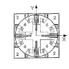
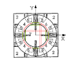
I shall try to explain using these diagrams. Honestly, I got it the second time looking through the diagrams on the first page.
Okay, first, this works exactly with the same principle as the pin mod, making the center piece catch on an attachment on the rivet/screw, causing the center to turn along with the center piece its caught on to.
In the first picture, it shows a rivet/screw with the attachment. From what I think it is from very brief reading, its a metal piece that is soldered or whatever onto the rivet/screw. The next picture(to its right) shows how a center piece sits on the rivet/screw with the attachment.
Notice how the pin mod creates a sort of track under the center piece? This is the same, except you just cut of a chunk right away.
The next picture(to its right) shows which 1/4 of the rivets/screws this attachment is put on.
The picture below it, shows how it works. When turning a layer, one center piece will catch on to the attachment. This will cause the center piece to stick to that center piece, much like how the pin mod works. The other center pieces are then free to move around.
The 2 pictures on the right most show what happens when the layer that sits on the rivet/screw is turned. Remember that chunk that was cut off? That will allow the attachment to simply slide under the centers when turned.
I hope this helps explain the mod. I can definitely see the ease of mass production with this way compared to mass producing with pin mods.

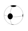


 I like the idea. Does anyone already has realized something like this ?