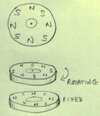
Has anyone seen this mod before?

7ombie

Regular
Joined
Oct 18, 2021
Messages
54
Location
Cambridgeshire, England
I had an idea for a mod, and wanted to ask if anyone has proposed it before. If it's original, I'll develop it more, then publish something similar to the PDF I shared a few days ago.

In its simplest form, the idea is to fix four magnets to the bottom of each center-piece, one in each corner, with four corresponding magnets (polarized to attract) immediately below the center-piece, in a tray that is fixed to the bolt (so it does not rotate when the center-piece rotates above it).

These images are simplistic, but illustrate how the magnets are arranged, and how the center-piece rotates above the tray, independently.


CLTM_basic.png
CLTM_basic_turn.png

I have some ideas for moving the magnets closer to the bolt (making the tray much smaller), for integrating the mod with maglev and reusing some of the magnets for both systems (maybe using pole-pieces for optimization), and possibly using magnetic strips (in an X shape, with the bolt through the middle) instead of round magnets. I also have some ideas for making everything adjustable still. I just don't know if the underlying mechanism is even novel.

Has anyone seen anything like this before?
 
This mod would be very similar in its effect to the system that GAN introduced for their 11th generation Pro and Duo cubes. Both systems reduce the radius of the rotation (of the magnets about their axis), allowing the system to correct much larger misalignments, but far less precisely. As such, both systems depend on the regular magnets (that correct much smaller misalignments with much higher precision) to finish the job of aligning the faces.

While this mod appears to use three times as many magnets (48 to 16) to achieve the same effect as the GAN system, and with about the same amount of force (on faces and slices) all other things being equal, it is not that simple, and there are advantages to this approach.

The GAN system can only be adjusted by disassembling the cube and replacing the eight magnetic rods with a different set. They provide two sets (meaning they actually need 32 magnets), and they still only have two levels of customization. The mod I'm proposing (once it is properly developed) would be customized by raising the magnets in the bottom of the center-piece (without needing to move the tray), then adjusting the height of the bolt-head. This would permit much finer adjustment, without having to disassemble the cube.

Given that the cube will likely use maglev in practice too, and that the magnets on the bottom of the center-pieces can be set up to attract the magnets below them, while simultaneously repelling a ring-magnet above them, the mod would eliminate half of the ring-magnets (or at least allow them to be much smaller, acting more like pole-pieces).

Note: So long as one of the two rails in a maglev system is a ring-magnet, the other rail can be made from three or more discrete magnets, placed at equidistant points opposite to the ring-magnet, and the effect will be just as consistent as using two ring-magnets (just like a stool with three or more legs).

All things considered, the two systems each have their own pros and cons, but would be pretty comparable overall.
 
Last edited:
I've been playing around with a few ideas, and came up with this design, which has some novel features that are not obvious at first:

CLML02D.png


Below is the same model, but in 3D:

CLML03D.png


The tray has been removed altogether. Now, for each face, there are four rod-magnets extending from the core, with four more reaching down from underneath the center-piece, and a single ring-magnet on the top of the stack.

Note that the repulsive force generated by the four rod-magnets in the bottom of each center-piece is boosted by the core magnets when the face is aligned. This causes the tension in the maglev system to lower as the face being tensioned rotates towards the mid-turn, and to rise again as the face moves beyond the mid-turn, peaking when the face is square. It's difficult to illustrate how this would affect corner-cuts (in each direction), as well as regular face and slice turns, but if you spend some time rotating a cube and thinking about when the tension rises and falls, it becomes apparent that the effect should be consistently desirable (and it can be easily dampened or enhanced).

The image depicts the magnets around the core as shorter than the magnets in the center-pieces to represent their relative strengths (in practice, varying the magnetization would also work). The optimal ratio between the strength of the core magnets and the strength of the magnets in the bottoms of the center-pieces would be subjective, but in general, keeping the core magnets relatively weak, will minimize the boosting effect they have on the maglev system (so the tension it generates will be more consistent throughout the turn).

The satisfying way that the rod-magnets will snap together when the cube is square, would become an undesirable initial resistance (similar to opening a fridge door) if the same effect prevented the center-pieces from rising smoothly during a corner-cut. The tension needs to increase smoothly as the deformation of the cube increases. Fortunately, the rod-magnets only align when the cube is square, so there will be no snap during a corner-cut (for either face).

Another concern with the design depicted above is the strong repulsive force at the very core of the cube, where there are 24 rod-magnets, all pointing the same pole at one another. However, we can easily make the force much weaker and attractive by flipping the polarity of the magnets for each opposite face, as in the version below:

CLML13D.png


Now, each stack of magnets (for each face) meet with three attractive stacks and two repulsive stacks at the core.

Obviously, this version of the mod is complicated, and there are lots of little things that could be adjusted, so while I've tried to preempt how the magnets would interact in various situations, without a prototype, it's all very vague and presumptive. After Christmas, I will be able to order some 3D printed parts, but can't afford to do that at the moment.

Note: The original idea doesn't need to be implemented in such a complicated way. I only wanted to share this version, as I thought the community might find using maglev to vary the tension through the turn interesting in itself.
 
I've been playing around with a few ideas, and came up with this design, which has some novel features that are not obvious at first:

View attachment 17607

Below is the same model, but in 3D:

View attachment 17608

The tray has been removed altogether. Now, for each face, there are four rod-magnets extending from the core, with four more reaching down from underneath the center-piece, and a single ring-magnet on the top of the stack.

Note that the repulsive force generated by the four rod-magnets in the bottom of each center-piece is boosted by the core magnets when the face is aligned. This causes the tension in the maglev system to lower as the face being tensioned rotates towards the mid-turn, and to rise again as the face moves beyond the mid-turn, peaking when the face is square. It's difficult to illustrate how this would affect corner-cuts (in each direction), as well as regular face and slice turns, but if you spend some time rotating a cube and thinking about when the tension rises and falls, it becomes apparent that the effect should be consistently desirable (and it can be easily dampened or enhanced).

The image depicts the magnets around the core as shorter than the magnets in the center-pieces to represent their relative strengths (in practice, varying the magnetization would also work). The optimal ratio between the strength of the core magnets and the strength of the magnets in the bottoms of the center-pieces would be subjective, but in general, keeping the core magnets relatively weak, will minimize the boosting effect they have on the maglev system (so the tension it generates will be more consistent throughout the turn).

The satisfying way that the rod-magnets will snap together when the cube is square, would become an undesirable initial resistance (similar to opening a fridge door) if the same effect prevented the center-pieces from rising smoothly during a corner-cut. The tension needs to increase smoothly as the deformation of the cube increases. Fortunately, the rod-magnets only align when the cube is square, so there will be no snap during a corner-cut (for either face).

Another concern with the design depicted above is the strong repulsive force at the very core of the cube, where there are 24 rod-magnets, all pointing the same pole at one another. However, we can easily make the force much weaker and attractive by flipping the polarity of the magnets for each opposite face, as in the version below:

View attachment 17611

Now, each stack of magnets (for each face) meet with three attractive stacks and two repulsive stacks at the core.

Obviously, this version of the mod is complicated, and there are lots of little things that could be adjusted, so while I've tried to preempt how the magnets would interact in various situations, without a prototype, it's all very vague and presumptive. After Christmas, I will be able to order some 3D printed parts, but can't afford to do that at the moment.

Note: The original idea doesn't need to be implemented in such a complicated way. I only wanted to share this version, as I thought the community might find using maglev to vary the tension through the turn interesting in itself.

Cool renderings.
I also loved the elite2 document that you shared a few days ago.
Lot of cool ideas there.
 
@TheCubingCuber347 - It's crazy how many mods are possible. We'll obviously need to find the best subsets, but it would be fun to just throw everything at a QiYi Warrior - n52s everywhere!

Personally, I call these things tractor stacks, to compliment the terms tractor matrix and (for the 11th-gen GAN system) tractor array (which uses tractor rods around a tractor core).

I also use the terms wide-beam and narrow-beam to describe the sweep (the angular breadth) of the tractor beams generated by a given tractor system. A standard matrix is a narrow-beam system, as it corrects small misalignments (but with high precision), while the GAN array is wide-beam (as it basically does the opposite).

I like to keep the names for the various subsystems nice and consistent, for my own sanity, but hotrod is a neat name for this, as a complete, fully implemented mod.

@abunickabhi - Thank you. That's very kind. It's really nice to know that people have enjoyed reading it.

By the way, the renderings are all done with Tinkercad, which is childsplay to use (even easier than SketchUp), and runs in the browser. You can just pick it up intuitively, and it has a button to toggle between an isometric perspective and a full 3D perspective, which I use to do all the 2D maps and whatnot. It's mainly used to create models, then 3D print them (locally, if you have a machine, or you can pick a company to mail them to you - and Tinkercad has a similar tool for creating custom PCBs). It's all very limited (even more than SketchUp), compared to serious, professional CAD software, but it still has all the essential primitives.

Thanks again, guys. Much appreciated.
 
Last edited:
One simplification I immediately thought of:
Magnets aren't restricted to being simply 'north and south' , it's possible to have multiple changes in polarity on a single magnet. This is common with ferrite magnets, it's pretty tricky ( possibly impractical ) for rare-earth NIB / SmCo's. It's used in some motors, for example flat ones in floppy disk drives.
For this application, a disc-shaped magnet could be magnetised N-S-N-S at 45 degree intervals, that is:
12 o'clock = N
1:30 pm = S
3:00 pm = N
4:30 pm = S etc.
Now if two of these are placed above each other, they will attract and align in one of the 90 degree positions. If you rotate one by 30 degrees, for example, it will magnetically pull back to the original position; if you rotate by 60 degrees, it will magnetically advance to 90 degrees.
So fixing one to the cube core, and one to the centre-piece would give quarter-turn indexing.

However, I'm not convinced of it's effectiveness ... being close to the core makes such a system less forceful than one out in the corner/edge pieces.
 

Attachments

  • CubeMag7584.jpg
    CubeMag7584.jpg
    11.3 KB · Views: 2
@abunickabhi - I'm installing FreeCAD now. I'd like to learn to use something more professional, and would only really invest that kind of effort in something open source. Thanks for the pointer. It looks awesome.

OnShape looks really impressive. I hadn't seen that before.

I didn't know you work on PCBs. I bought a bunch of electronics stuff, and have been meaning to learn it for a few years, but it's still just sat in the corner. I feel ignorant not knowing the essential stuff, like what capacitors or transistors even are.

@SenorJuan - Thanks for helping out.

I have considered using arc-magnets, but I was only really thinking to use the magnets for the shape (arranging four of them like petals around the bolt). I hadn't considered keeping them packed together and flipping half. That could work really well, assuming the magnets could be arranged like that. To be honest, if the polarities alternate, I don't understand why the magnets would not sit together quite happily. The north poles would be immediately adjacent to the south poles of the magnets on either side, so they should all attract (though that would also lower the force on nearby magnets). I don't understand this stuff very well.

By the way, the plan was always to have the regular 48 magnets far from the core as well (or something like that). These magnets were meant to prevent the face from stopping just shy of the point where the regular magnets can interact with it.

@Ninjascoccer - The ring-magnet at the top of each stack is one half of the maglev system. The four rod-magnets in the bottom of the center-piece will repel the ring-magnet above them and attract the rod-magnets below them.

One thing that might be a bigger problem than I first thought is just finding space around the bolt for the magnets. Most cube designs leave a small space, but once the pieces start moving, some of that space is crossed through by passing pieces, so there is only a couple of millimeters spare. The magnets in the image are way bigger than they need to be, but space is still going to be an issue.
 
Back
Top